
S/SX1800
180 mm
104 - 110 mm
180 - 1000 mm
265 - 1300 mm
Stay Variants
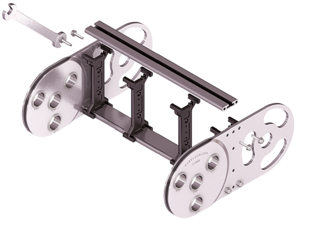
S/SX1800 RM
Frame stay, solid
- Aluminum profile bars for heavy loads and maximum cable carrier widths. Double threaded joint on both sides “Heavy Duty”.
- Inside/outside: Threaded joints easy to release.
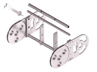
S/SX1800 RR
Frame stay, tube version
- Steel rolling stays with gentle cable support and steel dividers. Ideal for using media hoses with soft sheathing.
- Inside/outside: Screw connection detachable.
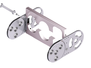
S/SX1800 LG
Frame stay, split
- Optimum cable routing in the neutral bending line. Split version for easy cable routing. Stays also available unsplit.
- Inside/outside: Threaded joint easy to release.

S/SX tubes
Also available as covered variants with cover system or steel band cover.
Installation dimensions
UNSUPPORTED ARRANGEMENT

| KR [mm] | H [mm] | LB [mm] | UB [mm] |
|---|---|---|---|
| 265 | 740 | 1552 | 695 |
| 320 | 850 | 1725 | 750 |
| 375 | 960 | 1898 | 805 |
| 435 | 1080 | 2087 | 865 |
| 490 | 1190 | 2259 | 920 |
| 605 | 1420 | 2620 | 1035 |
| 720 | 1650 | 2982 | 1150 |
| 890 | 1990 | 3516 | 1320 |
| 1175 | 2560 | 4411 | 1605 |
| 1300 | 2810 | 4804 | 1730 |
Installation height Hz: Hz = H + 10 mm/m
LOAD DIAGRAM FOR UNSUPPORTED LENGTH
depending on the additional load.
Intrinsic cable carrier weight qk = 26 kg/m. For other inner widths, the maximum additional load changes.
Speed
up to 2 m/s
Acceleration
up to 3 m/s2
Travel length
up to 17.8 m
Additional load
up to 60 kg/m

GLIDING ARRANGEMENT

Speed
up to 0.8 m/s
Acceleration
up to 2 m/s2
Travel length
on request
Additional load
up to 60 kg/m
The gliding cable carrier must be guided in a channel.
Glide shoes have to be used for gliding applications.
Special designs

S/SX1802 – with closed stroke system and straight link plates
- Closed stroke system protected between link plates mounted on both sides.
- Symmetrical side band design.
- Long service life even under the toughest conditions, e.g. large amounts of foundry sand, emery or scale thanks to optimized cable carrier geometry.

S/SX1802 B – with internal stroke system and straight link plates
- Open stroke system.
- Link plates of the side bands are mounted offset.
- Long service life even under the toughest conditions, e.g. large amounts of foundry sand, emery or scale thanks to optimized cable carrier geometry.
- The optimized, “self-cleaning” geometry prevents blocking of the stops through dirt.
- Version with bolted side bands.