
MT0650
65 mm
38.5 mm
50 - 500 mm
95 - 350 mm
Stay Variants
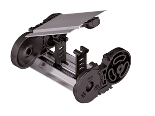
MT0650 RMD
Cover with hinge in the outer radius “standard”
- Aluminum cover system with hinge for light and medium loads. Assembly without screws.
- Outside: swivable to both sides.
- Inside: release by turning 90°.
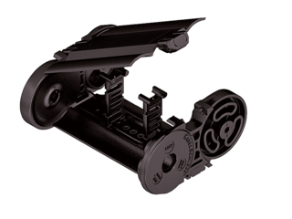
MT0650 RDD
Cover with hinge in the outer radius “standard”
- Plastic cover system with hinge for light and medium loads. Assembly without screws.
- Outside: swivable to both sides.
- Inside: release by turning by 90°.
Installation dimensions
UNSUPPORTED ARRANGEMENT

| KR [mm] | H [mm] | Hz [mm] | LB [mm] | UB [mm] |
|---|---|---|---|---|
| 95* | 247 | 282 | 429 | 189 |
| 115 | 287 | 322 | 492 | 209 |
| 145 | 347 | 382 | 586 | 239 |
| 175 | 407 | 442 | 680 | 269 |
| 220 | 497 | 532 | 822 | 314 |
| 260 | 577 | 612 | 948 | 354 |
| 275 | 607 | 642 | 994 | 369 |
| 300 | 657 | 692 | 1073 | 394 |
| 350 | 757 | 792 | 1230 | 444 |
* not RMD
LOAD DIAGRAM FOR UNSUPPORTED LENGTH
depending on the additional load.
Sagging of the cable carrier is technically permitted for extended travel lengths, depending on the specific application.
Intrinsic cable carrier weight qk = 3.5 kg/m. For other inner widths, the maximum additional load changes.
Speed
up to 10 m/s
Acceleration
up to 35 m/s2
Travel length
up to 4.8 m
Additional load
up to 25 kg/m

GLIDING ARRANGEMENT
GO module with chain links optimized for gliding

| KR [mm] | H [mm] | GO module RKR [mm] | LB [mm] | UB [mm] |
|---|---|---|---|---|
| 95* | 171 | 300 | 1180 | 560 |
| 115 | 171 | 300 | 1310 | 605 |
| 145 | 171 | 300 | 1440 | 640 |
| 175 | 171 | 300 | 1635 | 705 |
| 220 | 171 | 300 | 1950 | 810 |
| 260 | 171 | 300 | 2275 | 926 |
| 275 | 171 | 300 | 2405 | 973 |
| 350 | 171 | 300 | 2925 | 1152 |
* not RMD
Speed
up to 8 m/s
Acceleration
up to 20 m/s2
Travel length
up to 170 m
Additional load
up to 25 kg/m
The gliding cable carrier must be guided in a channel.
The GO module mounted on the driver is a defined sequence of 5 adapted KR/RKR link plates.
Glide shoes have to be used for gliding applications.