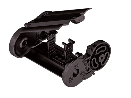
MT0650 RDD
Plastic cover RDD – cover with hinge in the outer radius

Properties
- Plastic cover system with hinge for light and medium loads. Assembly without screws.
- Available customized in 8 mm sections.
- Outside: swivable to both sides.
- Inside: release by turning 90°.

Dimensions Dimensions

| Bi [mm] * | |||||||||
|---|---|---|---|---|---|---|---|---|---|
| 50 | 58 | 66 | 74 | 82 | 90 | 98 | 106 | 114 | 122 |
| 130 | 138 | 146 | 154 | 162 | 170 | 178 | 186 | 194 | 202 |
| 210 | 218 | 226 | 234 | 242 | 250 | 258 | |||
| KR [mm] | ||||||||
|---|---|---|---|---|---|---|---|---|
| 95 | 115 | 145 | 175 | 220 | 260 | 275 | 300 | 350 |
Order example
Inner Distribution Inner Distribution
Divider systems
As a standard, the divider system is assembled at every 2nd chain link.
For applications with lateral acceleration and laying on the side, the dividers or the complete divider system (dividers with height separations) are fixed in the cross section. The arresting cams click into place in the locking grids in the crossbars (version B).
Divider system TS0
without height separation
| Vers. | aT min [mm] | ax min [mm] | ac min [mm] | ax grid [mm] | nT min |
|---|---|---|---|---|---|
| B | 13 | 16 | 11.8 | 8 | – |
The dividers are fixed in the cross section (version B).

Divider system TS1
with continuous height separation
| Vers. | aT min [mm] | aT max [mm] | ax min [mm] | ac min [mm] | ax grid [mm] | nT min |
|---|---|---|---|---|---|---|
| B | 13 | 21 | 16 | 11.8 | 8 | 2 |
The dividers are fixed in the cross section (version B).

Order example
Please state the designation of the divider system (TS0, TS1,...), the version, and the number of dividers per cross section [nT].
When using divider systems with height separation (TS1), please additionally state the position (e.g. VD1) viewed from the left driver belt. You are welcome to add a sketch to your order.
End connectors End connectors


Connection point
F – fixed point
M – driver
Connection type
U – Universal end connector
Order example
We recommend the use of strain reliefs at the driver and fixed point.


Connection point
F – fixed point
M – driver
Connection type
A – threaded joint outside (standard)
I – threaded joint inside
F – flange connection
Connection surface
A – connection surface outside
I – connection surface inside

Order example
We recommend the use of strain reliefs at the driver and fixed point.
