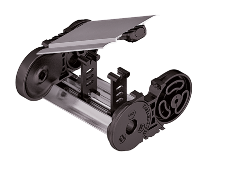
MT0650 RMD
Aluminum cover RMD – cover with hinge in the outer radius

Properties
- Aluminum cover system with hinge for light and medium loads. Assembly without screws.
- Available customized in 1 mm sections.
- Outside: swivable to both sides.
- Inside: release by turning 90°.

Dimensions Dimensions

| KR [mm] | |||||||
|---|---|---|---|---|---|---|---|
| 115 | 145 | 175 | 220 | 260 | 275 | 300 | 350 |
Order example
Inner Distribution Inner Distribution
Divider systems
As a standard, the divider system is mounted on every 2nd chain link.
As a standard, dividers or the complete divider System (dividers with height separations) are movable in the cross section (version A).
Divider system TS0
without height separation
| Vers. | aT min [mm] | ax min [mm] | ac min [mm] | nT min |
|---|---|---|---|---|
| A | 16 | 13 | 10 | – |
The dividers can be moved in the cross section.

Divider system TS1
with continuous height separation
| Vers. | aT min [mm] | aT max [mm] | ax min [mm] | ac min [mm] | nT min |
|---|---|---|---|---|---|
| A | 16 | 40 | 13 | 10 | 2 |
The dividers can be moved in the cross section.

Order example
Please state the designation of the divider system (TS0, TS1 …), version and number of dividers per cross section [nT].
If using divider systems with height separation (TS1) please also state the positions [e.g. VD1] viewed from the left driver belt. You are welcome to add a sketch to your order.
End connectors End connectors


Connection point
F – fixed point
M – driver
Connection type
U – Universal end connector
Order example
We recommend the use of strain reliefs at the driver and fixed point.


Connection point
F – fixed point
M – driver
Connection type
A – threaded joint outside (standard)
I – threaded joint inside
F – flange connection
Connection surface
A – connection surface outside
I – connection surface inside

Order example
We recommend the use of strain reliefs at the driver and fixed point.
