
UA1995
99.5 mm
80 mm
66 - 600 mm
150 - 500 mm
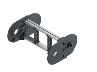
Stay Variants
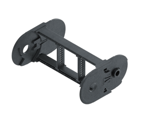
UA1995.020
Closed frame
- Weight-optimised, closed plastic frame with particularly high torsional rigidity.
- Outside/inside: not openable.
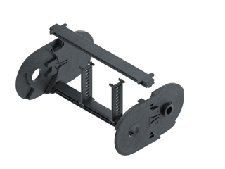
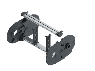
UA1995.030
Frame with outside detachable stays
- Weight-optimised plastic frame with particularly high torsional rigidity.
- Outside: release by rotating 90°.
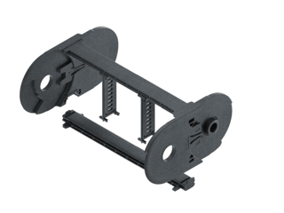
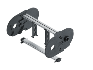
UA1995.040
Frame with inside detachable stays
- Weight-optimised plastic frame with particularly high torsional rigidity.
- Inside: release by rotating 90°.
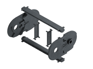
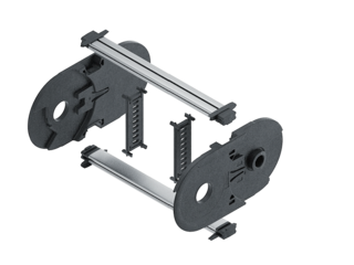
UA1995.070
Frame with outside and inside detachable stays
- Weight-optimised plastic frame with particularly high torsional rigidity.
- Outside/inside: release by rotating 90°.
UA1995 RSH 020
Stay variant RSH 020 – closed frame
UA1995 RSH 030
Stay variant RSH 030 – with outside detachable stays
UA1995 RSH 040
Stay variant RSH 040 – with inside detachable stays
UA1995 RSH 070
Stay variant RSH 070 – with outside and inside detachable stays
Installation dimensions
UNSUPPORTED ARRANGEMENT

| KR [mm] | H [mm] | Hz [mm] | LB [mm] | UB [mm] |
|---|---|---|---|---|
| 150 | 410 | 440 | 680 | 250 |
| 210 | 530 | 560 | 860 | 310 |
| 250 | 610 | 640 | 990 | 350 |
| 300 | 710 | 740 | 1150 | 400 |
| 350 | 810 | 840 | 1300 | 450 |
| 400 | 910 | 940 | 1460 | 500 |
| 500 | 1110 | 1140 | 1770 | 600 |
LOAD DIAGRAM FOR UNSUPPORTED LENGTH
depending on the additional load.
Sagging of the cable carrier is technically permitted for extended travel lengths, depending on the specific application.
Intrinsic cable carrier weight qk = 3.85 kg/m with Bi 196 mm. For other inner widths, the maximum additional load changes.

Speed
up to 10 m/s

Acceleration
up to 25 m/s2

Travel length
up to 9 m

Additional load
up to 50 kg/m

GLIDING ARRANGEMENT
GO module with chain links optimized for gliding*
* only design 070

| KR [mm] | H [mm] | GO module RKR [mm] | LB [mm] | UB [mm] |
|---|---|---|---|---|
| 150 | 330 | 400 | 1805 | 890 |
| 210 | 330 | 400 | 2180 | 1010 |
| 250 | 330 | 400 | 2390 | 1070 |
| 300 | 330 | 400 | 2690 | 1160 |
| 350 | 330 | 400 | 3090 | 1310 |
| 400 | 330 | 400 | 3490 | 1450 |
| 500 | 330 | 400 | 4280 | 1740 |
Speed
up to 8 m/s
Acceleration
up to 20 m/s2
Travel length
up to 200 m
Additional load
up to 50 kg/m

The gliding cable carrier must be guided in a channel.
The GO module mounted on the driver is a defined sequence of 5 adapted KR/RKR link plates.
Glide shoes must be used for gliding applications.