
UA1455.020
Stay variant 020 – closed frame

Properties
- Weight-optimised, closed plastic frame with particularly high torsional rigidity.
- Outside/inside: not openable.

Dimensions Dimensions

| Bi [mm] | |||||
|---|---|---|---|---|---|
| 25 | 38 | 58 | 78 | 103 | 130 |
| KR [mm] | ||||||
|---|---|---|---|---|---|---|
| 52 | 65 | 95 | 125 | 150 | 180 | 200 |
Order example
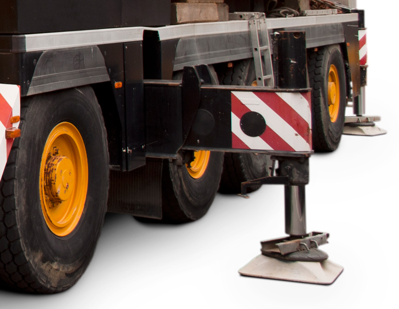 | Special version for support legs of commercial vehicles Special versions for the safe guiding and separating of rigid hydraulic hoses and electric cables in a limited space in extendable support feet of commercial vehicles on request. |
Inner Distribution Inner Distribution
Divider systems
The divider system is mounted on every 2nd chain link as a standard.
As a standard, dividers or the complete divider system (dividers with height separations) are movable in the cross section (version A).
Divider system TS0
without height separation
| Vers. | aT min [mm] | ax min [mm] | ac min [mm] | ax grid [mm] | nT min |
|---|---|---|---|---|---|
| A | 3.5 | 7 | 5 | – | – |
Number of dividers for design 020 depending on Bi

Order example
Please state the designation of the divider system (TS0), the version, and the number of dividers per cross section [nT]. You are welcome to add a sketch to your order.
End connectors End connectors


| Bi [mm] | nz |
|---|---|
| 25 | 2 |
| 38 | 3 |
| 58 | 5 |
| 78 | 7 |
| 103 | 9 |
| 130 | 11 |

The end connectors are optionally also available with strain relief comb (1 on each side). Please state when ordering.

Connection point
F – fixed point
M – driver
Connection type
U – Universal mounting bracket
Order example


| Bi [mm] | nz |
|---|---|
| 25 | 2 x 2 |
| 38 | 2 x 3 |
| 58 | 2 x 4 |
| 78 | 2 x 6 |
| 103 | 2 x 8 |
| 130 | 2 x 10 |

The end connectors are optionally also available without strain relief comb (except Bi 25). Please state when ordering.

Connection point
F – fixed point
M – driver
Connection type
A – threaded joint outside (standard)
I – threaded joint inside
H – threaded joint, rotated 90° to the outside
K – threaded joint, rotated 90° to the inside
Order example


| Bi [mm] | nz |
|---|---|
| 25 | 2 x 2 |
| 38 | 2 x 3 |
| 58 | 2 x 4 |
| 78 | 2 x 6 |
| 103 | 2 x 8 |
| 130 | 2 x 10 |

The end connectors are optionally also available without strain relief comb (except Bi 25). Please state when ordering.
Connection point
F – fixed point
M – driver
Connection type
A – threaded joint outside (standard)
I – threaded joint inside
H – threaded joint, rotated 90° to the outside
K – threaded joint, rotated 90° to the inside