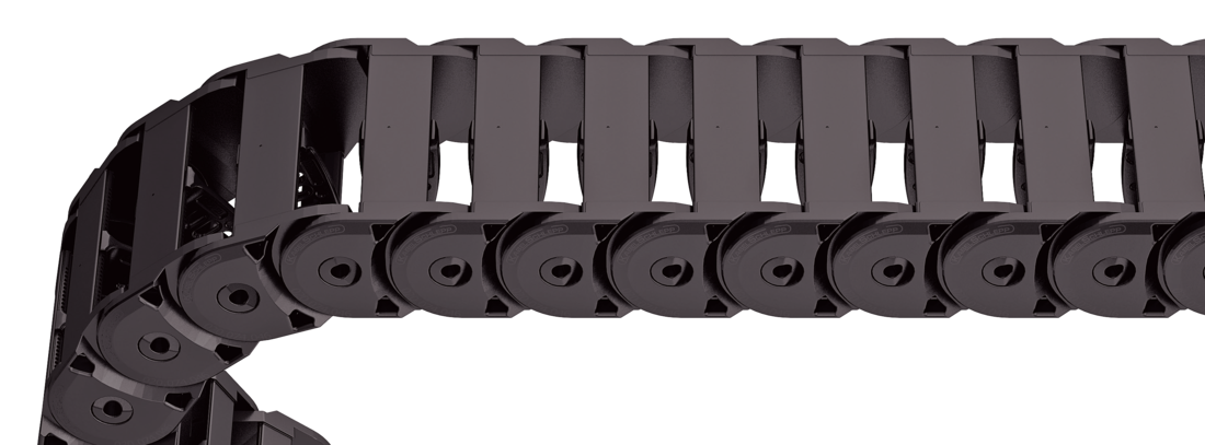
Weight-optimised, closed plastic frame with particularly high torsional rigidity.
Outside/inside: closed.
Stay arrangement on each chain link (VS: fully-stayed)
Bi
39 - 99
mm
Dimensions
Dimensions
The maximum cable diameter strongly depends on the bending radius and the desired cable type. Please contact us.
Calculating the cable carrier length
Cable carrier length Lk: Lk ≈ LS/2 + LB
Cable carrier length Lk rounded to pitch t
<table class="table">
<thead>
<tr>
<!-- Reihenfolge gemäß Kundenwunsch -->
<th class="t"><strong>t</strong><br>[mm]</th>
<th class="hi red"><strong>h<sub>i</sub></strong><br>[mm]</th>
<th class="hg"><strong>h<sub>G</sub></strong><br>[mm]</th>
<!-- Bi Spalte nur anzeigen wenn einzelner Wert oder Range -->
<!-- Bk und BEF für alle Ketten -->
<th class="bk"><strong>B<sub>k</sub></strong><br>[mm]</th>
<!-- KR Spalte nur anzeigen wenn einzelner Wert oder Range -->
<th class="qk"><strong>q<sub>k</sub></strong><br>[kg/m]</th>
</tr>
</thead>
<tbody>
<tr>
<!-- Reihenfolge gemäß Kundenwunsch -->
<td class="t">39</td>
<td class="hi red">39</td>
<td class="hg">50</td>
<!-- Bi Spalte nur anzeigen wenn einzelner Wert oder Range -->
<!-- Bk und BEF für alle Ketten -->
<td class="bk">Bi + 21</td>
<!-- KR Spalte nur anzeigen wenn einzelner Wert oder Range -->
<td class="qk">1.29 – 1.71</td>
</tr>
</tbody>
</table>
Bi [mm]
39
59
74
99
KR [mm]
46
58
70
95
Order example
TKK39
Type
•
020
Stay variant
•
74
Bi [mm]
•
70
KR [mm]
-
1950
Lk [mm]
VS
Stay arrangement
Inner Distribution
Inner Distribution
Divider systems
The divider system is mounted on every 2nd chain link as a standard.
Dividers, and the complete divider system (dividers with height separations) comes as diameter adjustable as standard (version A).
Divider system TS0 without height separation
Vers.
aT min [mm]
ax min [mm]
ac min [mm]
ax grid [mm]
nT min
A
5
10
7
–
–
The dividers can be moved in the cross section.
Order example
TS0
Divider system
•
A
Version
•
3
nT
Please state the designation of the divider system (TS0), the version, and the number of dividers per cross section [nT].
End connectors
End connectors
Connection point F – fixed point M– driver
Connection type A – connecting surface outside I – connecting surface inside
Connection surface A – threaded joint outside (standard) I – threaded joint inside
Order example
Steel
Steel
End connector
•
F
•
M
Connection point
A
A
Connection type
I
I
Connection surface
We recommend the use of strain reliefs at the driver and fixed point.