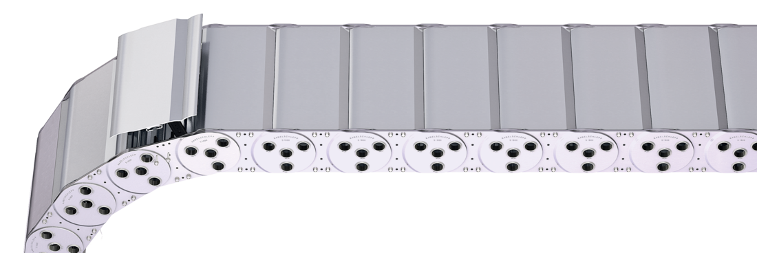
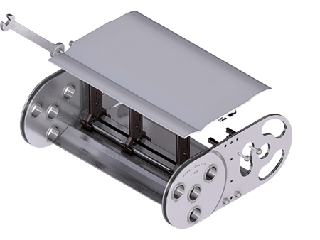
S/SX1800 Tubes RMD
Aluminum stay RMD – aluminum cover system

Properties
- Bolted aluminum covers for maximum stability.
- For applications generating chips or coarse contamination.
- Available customized in 1 mm grid.
- Inside/outside: Threaded joint easy to release.

Dimensions Dimensions

| KR [mm] | ||||||||
|---|---|---|---|---|---|---|---|---|
| 320 | 375 | 435 | 490 | 605 | 720 | 890 | 1,175 | 1,300 |
Order example
Inner Distribution Inner Distribution
Divider systems
As a standard, the divider system is mounted on every 2nd cover/chain link (HS).
As a standard, dividers or the complete divider system (dividers with height separations) are movable in the cross section (version A).
Divider system TS0
without height separation
| Vers. | aT min [mm] | ax min [mm] | ac min [mm] | nT min |
|---|---|---|---|---|
| A | 21.5 | 25 | 17.5 | – |
The dividers can be moved in the cross section.

Divider system TS1
with continuous height separation
| Vers. | aT min [mm] | ax min [mm] | ac min [mm] | nT min |
|---|---|---|---|---|
| A | 21.5 | 25 | 17.5 | 2 |
The dividers can be moved in the cross section.

Divider system TS3
with height separation consisting of plastic partitions
| Vers. | aT min [mm] | ax min [mm] | ac min [mm] | nT min |
|---|---|---|---|---|
| A | 38*/16.5**/12*** | 16/42* | 8 | 2 |
* For aluminum partitions
** For VR0
*** For version with height separation to the end divider
The dividers are fixed with the partitions. The entire divider system can be moved in the cross section.


Aluminum partitions in 1 mm increments with ax > 42 mm are also available.
ax (center distance of dividers) [mm] | |||||||||||
ac (nominal width of inner chamber) [mm] | |||||||||||
| 16 | 18 | 23 | 28 | 32 | 33 | 38 | 43 | 48 | 58 | 64 | 68 |
| 8 | 10 | 15 | 20 | 24 | 25 | 30 | 35 | 40 | 50 | 56 | 60 |
| 78 | 80 | 88 | 96 | 112 | 128 | 144 | 160 | 176 | 192 | 208 | |
| 70 | 72 | 80 | 88 | 104 | 120 | 136 | 152 | 168 | 184 | 200 | |
When using plastic partitions with ax > 112 mm, we recommend an additional center support with a twin divider (ST = 5 mm). Twin dividers are also suitable for retrofitting in the partition system.
Order example
Please state the designation of the divider system (TS0, TS1 …), version and number of dividers per cross section [nT]. In addition, please also enter the chambers [K] from left to right, as well as the assembly distances [aT/ax] (as seen from the driver).
If using divider systems with height separation (TS1 - TS3), please also state the positions (e.g. VR23) viewed from the left driver belt. You are welcome to add a sketch to your order.
End connectors End connectors


Connection point
F – fixed point
M – driver
Connection type
A – threaded joint outside (standard)
I – threaded joint inside
H – threaded joint, rotated 90° to the outside
K – threaded joint, rotated 90° to the inside
Connection surface
A – connection surface inside (standard)
I – connection surface outside
Order example
We recommend the use of strain reliefs at the driver and fixed point.
