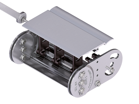
S/SX0650 Tubes RMD
Aluminum stay RMD – aluminum cover system

Properties
- Bolted aluminum covers for maximum stability.
- For applications generating chips or coarse contamination.
- Available customized in 1 mm grid.
- Inside/outside: Threaded joint easy to release.

Dimensions Dimensions

| KR [mm] | |||||||||
|---|---|---|---|---|---|---|---|---|---|
| 115 | 125 | 135 | 145 | 155 | 175 | 200 | 250 | 300 | 400 |
Order example
Inner Distribution Inner Distribution
Divider systems
As a standard, the divider system is mounted on every 2nd cover/chain link (HS).
As a standard, dividers or the complete divider system (dividers with height separations) are movable in the cross section (version A).
Divider system TS0
without height separation
| Vers. | aT min [mm] | ax min [mm] | ac min [mm] | nT min |
|---|---|---|---|---|
| A | 11.5 | 13 | 10 | – |
The dividers can be moved in the cross section.

Divider system TS1
with continuous height separation
| Vers. | aT min [mm] | ax min [mm] | ac min [mm] | nT min |
|---|---|---|---|---|
| A | 11.5 | 13 | 10 | 2 |
The dividers can be moved in the cross section.

Order example
Please state the designation of the divider system (TS0, TS1 …), version and number of dividers per cross section [nT].
If using divider systems with height separation (TS1) please also state the positions [e.g. VD1] viewed from the left driver belt. You are welcome to add a sketch to your order.
The end dividers are part of the divider system and don‘t have to be ordered separately.
End connectors End connectors


Connection point
F – fixed point
M – driver
Connection type
A – threaded joint outside (standard)
I – threaded joint inside
H – threaded joint, rotated 90° to the outside
K – threaded joint, rotated 90° to the inside
Connection surface
A – connection surface inside (standard)
I – connection surface outside
Order example
We recommend the use of strain reliefs at the driver and fixed point.
