
S/SX2500 RM
S/SX2500 RM
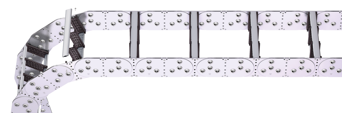
Aluminum stay RM – frame stay, solid

Properties
- Aluminum profile bars for heavy loads and maximum cable carrier widths. Double threaded joint on both sides “Heavy Duty”.
- Available customized in 1 mm grid.
- Inside/outside: Threaded joint easy to release.


Dimensions Dimensions

Calculating the cable carrier length
Cable carrier length Lk: Lk ≈ LS/2 + LB
Cable carrier length Lk rounded to pitch t for odd number of chain links
* in1 mm width sections
| KR [mm] | |||||||
|---|---|---|---|---|---|---|---|
| 365 | 445 | 600 | 760 | 920 | 1,075 | 1,235 | 1,395 |
Order example
S2500
Type
•
806
BSt [mm]
•
RM
Stay variant
•
760
KR [mm]
•
St
Material
-
9250
Lk [mm]
HS
Stay arrangement
Inner Distribution Inner Distribution
Divider systems
As a standard, the divider system is mounted on each crossbar – for stay mounting on every 2nd chain link (HS).
As a standard, dividers and the complete divider system (dividers with height separations) can be moved in the cross section (version A).
Divider system TS0
without height separation
| Vers. | aT min [mm] | ax min [mm] | ac min [mm] | nT min |
|---|---|---|---|---|
| A | 19 | 25 | 13 | – |
The dividers can be moved in the cross section.

Divider system TS1
with continuous height separation
| Vers. | aT min [mm] | ax min [mm] | ac min [mm] | nT min |
|---|---|---|---|---|
| A | 19 | 13 | 25 | 2 |
The dividers can be moved in the cross section.

Divider system TS2
with partial height separation
| Vers. | aT min [mm] | ax min [mm] | ac min [mm] | nT min |
|---|---|---|---|---|
| A | 40 | 46 | 34 | 2 |
Standard height separation with tube Ø 16 mm.
The dividers can be moved in the cross section.


Order example
TS2
Divider system
•
A
Version
•
2
nT
•
K1
•
K3
Chamber
•
34
•
38
ax
-
VR1
-
VR3
Height separation
End connectors End connectors


Connection point
F – fixed point
M – driver
Connection type
A – threaded joint outside (standard)
I – threaded joint inside
Order example
Steel
Steel
End connector
•
F
•
M
Connection point
A
A
Connection type
We recommend the use of strain reliefs at the driver and fixed point.