Skip to main navigation Skip to main content Skip to page footer
S/SX0950 RM

S/SX0950 RM

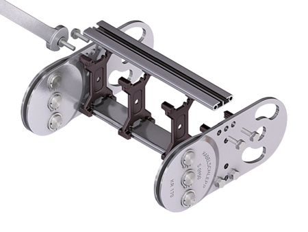
Aluminum stay RM – frame stay, solid
Properties

  • Aluminum profile bars for heavy loads and maximum cable carrier widths. Double threaded joint on both sides “Heavy Duty”.
  • Available customized in 1 mm grid.
  • Inside/outside: Threaded joints easy to release.
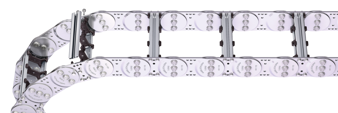
Stays on every 2<sup>nd</sup> section, <strong>standard (HS: half-stayed)</strong>
Stay arrangement on each chain link <strong>(VS: fully-stayed)</strong>
Bk 125 - 600 mm in 1 mm width sections

Dimensions Dimensions

The maximum cable diameter strongly depends on the bending radius and the desired cable type. Please contact us.
Calculating the cable carrier length
Cable carrier length Lk: Lk ≈ LS/2 + LB
Cable carrier length Lk rounded to pitch t
<table class="table"> <thead> <tr> <!-- Reihenfolge gemäß Kundenwunsch --> <th class="t"><strong>t</strong><br>[mm]</th> <th class="hi red"><strong>h<sub>i</sub></strong><br>[mm]</th> <th class="dmin"><strong>D<sub>min</sub></strong><br>[mm]</th> <th class="hg"><strong>h<sub>G</sub></strong><br>[mm]</th> <th class="hgdash"><strong>h<sub>G'</sub></strong><br>[mm]</th> <!-- Bi Spalte nur anzeigen wenn einzelner Wert oder Range --> <th class="bi"><strong>B<sub>i</sub></strong><br>[mm]</th> <th class="bst red"><strong>B<sub>St</sub></strong><br>[mm]<sup>*</sup></th> <!-- Bk und BEF für alle Ketten --> <th class="bk"><strong>B<sub>k</sub></strong><br>[mm]</th> <th class="bef"><strong>B<sub>EF</sub></strong><br>[mm]</th> <!-- KR Spalte nur anzeigen wenn einzelner Wert oder Range --> <th class="qk"><strong>q<sub>k</sub></strong><br>[kg/m]</th> </tr> </thead> <tbody> <tr> <!-- Reihenfolge gemäß Kundenwunsch --> <td class="t">95</td> <td class="hi red">43</td> <td class="dmin"></td> <td class="hg">68</td> <td class="hgdash">73</td> <!-- Bi Spalte nur anzeigen wenn einzelner Wert oder Range --> <td class="bi"> 88 - 563 </td> <td class="bst red"> 106 - 581 </td> <!-- Bk und BEF für alle Ketten --> <td class="bk">BSt + 19</td> <td class="bef">BSt + 28</td> <!-- KR Spalte nur anzeigen wenn einzelner Wert oder Range --> <td class="qk">7.78 - 10.68</td> </tr> </tbody> </table>
* in 1 mm width sections
KR [mm]
125 140 170 200 260 290 320 350 410 600

Order example

S0950
Type
150
BSt [mm]
RM
Stay variant
200
KR [mm]
St
Material
-
2375
Lk [mm]
HS
Stay arrangement

Inner Distribution Inner Distribution

Divider systems

The divider system is mounted on each crossbar as a Standard – on every 2nd chain link for stay mounting (HS).

As a standard, dividers or the complete divider System (dividers with height separations) are movable in the cross section (version A).

Divider system TS0
without height separation

Vers.aT min
[mm]
ax min
[mm]
ac min
[mm]
nT min
A101410

The dividers can be moved in the cross section.

Divider system TS1
with continuous height separation

Vers.aT min
[mm]
ax min
[mm]
ac min
[mm]
nT min
A1014102

The dividers can be moved in the cross section.

Order example

TS1
Divider system
A
Version
3
nT
-
VD0
-
VD1
Height separation

Please state the designation of the divider system (TS0, TS1 …), version and number of dividers per cross section [nT].

If using divider systems with height separation (TS1) please also state the positions [e.g. VD1] viewed from the left driver belt. You are welcome to add a sketch to your order. The end dividers are part of the divider system and don‘t have to be ordered separately.

End connectors End connectors

Connection point
F – fixed point
M – driver

Connection type
A – threaded joint outside (standard)
I – threaded joint inside
H – threaded joint, rotated 90° to the outside
K – threaded joint, rotated 90° to the inside

Connection surface
I – connection surface inside (standard)
A – connecting surface outside

Caution: The standard connection variant FAI/MAI is only possible from Bk of 122 mm.

Order example

Steel
Steel
End connector
F
M
Connection point
A
A
Connection type
I
I
Connection surface

We recommend the use of strain reliefs at the driver and fixed point.