M1300
M1300
Pitch
130 mm
130 mm
Inner heights
87 - 98 mm
87 - 98 mm
Inner widths
100 - 800 mm
100 - 800 mm
Bending radii
150 - 500 mm
150 - 500 mm
Stay Variants

MC1300 RMF
more details

MC1300 RMS
more details

MC1300 LG
more details
Stay Variants

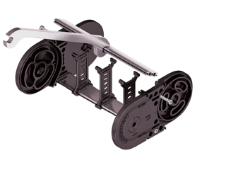
MC1300 RMF
Frame stay solid with optional fixing profile
- Aluminum profile bars for heavy loads and large cable carrier widths. Easy threaded connection.
- Inside/outside: Threaded joint easy to release.

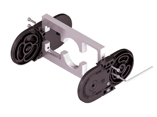
MC1300 RMS
Frame stay solid with ball joint
- Aluminum profile bars with plastic ball joint for heavy loads and large cable carrier widths. Assembly without screws.
- Inside/outside: Swivable and detachable.

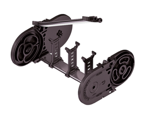
MC1300 LG
Hole stay, split version
- Optimum cable routing in the neutral bending line. Split version for easy cable routing. Stays also available unsplit.
- Outside/inside: Screw-fixing easy to release.
Installation dimensions


Installation dimensions
UNSUPPORTED ARRANGEMENT

| KR [mm] | H [mm] | Hz [mm] | LB [mm] | UB [mm] |
|---|---|---|---|---|
| 150 | 480 | 540 | 732 | 340 |
| 195 | 570 | 630 | 873 | 385 |
| 240 | 660 | 720 | 1014 | 430 |
| 280 | 740 | 800 | 1140 | 470 |
| 320 | 820 | 880 | 1266 | 510 |
| 360 | 900 | 960 | 1391 | 550 |
| 400 | 980 | 1040 | 1517 | 590 |
| 500 | 1180 | 1240 | 1831 | 690 |
LOAD DIAGRAM FOR UNSUPPORTED LENGTH
depending on the additional load.
Sagging of the cable carrier is technically permitted for extended travel lengths, depending on the specific application.
Intrinsic cable carrier weight qk = 8.0 kg/m. For other inner widths, the maximum additional load changes.

GLIDING ARRANGEMENT | GO MODULE
with chain links optimized for gliding

| KR [mm] | H [mm] | GO module RKR [mm] | LB [mm] | UB [mm] |
|---|---|---|---|---|
| 195 | 360 | 500 | 2210 | 1040 |
| 240 | 360 | 500 | 2470 | 1125 |
| 320 | 360 | 500 | 2880 | 1240 |
| 360 | 360 | 500 | 3140 | 1331 |
| 500 | 360 | 500 | 4310 | 1756 |
The GO module mounted on the driver is a defined sequence of 4 adapted KR/RKR link plates.
Glide shoes are required for gliding applications.


