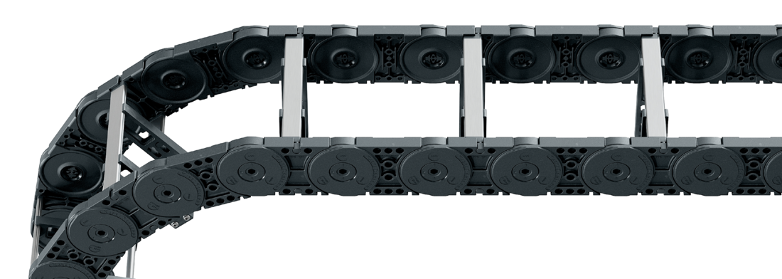
Aluminum profile bars with plastic mounting frame stays for guiding very large cable diameters.
The mounting frame stay is mounted on the inside in the bending radius.
Available customized in 1 mm width sections.
Inside: Screw-fixing easy to release.
Stays on every 2nd section, standard (HS: half-stayed)
Stay arrangement on each chain link (VS: fully-stayed)
Bi
200 - 800
mm
in 1 mm width sections
Dimensions
Dimensions
<p>The maximum cable diameter strongly depends on the bending radius and the desired cable type. Please contact us.</p>
<p><strong>Intrinsic cable carrier weight</strong><br />Determining the intrinsic cable carrier weight strongly depends on the selected stay arrangement. Please contact us.</p>
Calculating the cable carrier length
Cable carrier length Lk: Lk ≈ LS/2 + LB
Cable carrier length Lk rounded to pitch t
<table class="table">
<thead>
<tr>
<!-- Reihenfolge gemäß Kundenwunsch -->
<th class="t"><strong>t</strong><br>[mm]</th>
<th class="hi red"><strong>h<sub>i</sub></strong><br>[mm]</th>
<th class="hg"><strong>h<sub>G</sub></strong><br>[mm]</th>
<!-- Bi Spalte nur anzeigen wenn einzelner Wert oder Range -->
<th class="bi red"><strong>B<sub>i</sub></strong><br>[mm]<sup>*</sup></th>
<!-- Bk und BEF für alle Ketten -->
<th class="bk"><strong>B<sub>k</sub></strong><br>[mm]</th>
<th class="bef"><strong>B<sub>EF</sub></strong><br>[mm]</th>
<!-- KR Spalte nur anzeigen wenn einzelner Wert oder Range -->
</tr>
</thead>
<tbody>
<tr>
<!-- Reihenfolge gemäß Kundenwunsch -->
<td class="t">125</td>
<td class="hi red">72</td>
<td class="hg">96</td>
<!-- Bi Spalte nur anzeigen wenn einzelner Wert oder Range -->
<td class="bi red">
200 - 800
</td>
<!-- Bk und BEF für alle Ketten -->
<td class="bk">Bi + 45</td>
<td class="bef">Bi + 45</td>
<!-- KR Spalte nur anzeigen wenn einzelner Wert oder Range -->
</tr>
</tbody>
</table>
* in1 mm width sections
Hi [mm]
130
160
200
KR [mm]
180
220
260
300
340
380
500
Order example
MC1250
Type
•
400
Bi [mm]
•
RMAI
Stay variant
•
300
KR [mm]
-
4250
Lk [mm]
HS
Stay arrangement
RMAI – assembly to the inside:
Gliding application is not possible when using assembly version RMAI. Observe minimum KR: Hi = 130 mm: KRmin = 180 mm Hi = 160 mm: KRmin = 180 mm Hi = 200 mm: KRmin = 220 mm
End connectors
End connectors
Recommended tightening torque: 54 Nm for cheese-head screws ISO 4762 - M10 - 8.8
Connection point F – fixed point M – driver
Connection type U – universal mounting bracket
Order example
UMB
UMB
End connector
•
F
•
M
Connection point
U
U
Connection type
We recommend the use of strain reliefs at the driver and fixed point.
Connection point F – fixed point M – driver
Connection type A – threaded joint outside (standard) I – threaded joint inside F – flange connection
Connection surface I – connection surface inside A – connection surface outside
Order example
Plastic/steel
Plastic/steel
End connector
F
M
Connection point
A
A
Connection type
A
I
Connection surface
We recommend the use of strain reliefs at the driver and fixed point.