
LS/LSX1050 RR
LS/LSX1050 RR
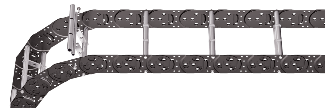
Tube stay RR – frame stay, tube version

Properties
- Steel rolling stays with gentle cable support and steel dividers. Ideal for using media hoses with soft sheathing. Easy screw connection.
- Available customized in 1 mm width sections.
- Inside/outside: Screw connection detachable
- Option: Divider systems made from steel and stainless steel ER 1, ER 1S.

Dimensions Dimensions

Calculating the cable carrier length
Cable carrier length Lk: Lk ≈ LS/2 + LB
Cable carrier length Lk rounded to pitch t
* in1 mm width sections
| KR [mm] | ||||||||
|---|---|---|---|---|---|---|---|---|
| 105 | 125 | 155 | 195 | 260 | 295 | 325 | 365 | 430 |
Order example
LS1050
Type
•
180
BSt [mm]
•
RR
Stay variant
•
125
KR [mm]
•
Sb
Material
-
2415
Lk [mm]
HS
Stay arrangement
Inner Distribution Inner Distribution
Divider systems
As a standard, the divider system is mounted on each crossbar – for stay mounting on every 2nd chain link (HS).
The dividers are fixed through the tubes. The tube additionally serves as a spacer between the dividers (version B).
Divider system TS0
without height separation
| Vers. | aT min [mm] | ax min [mm] | ac min [mm] | nT min |
|---|---|---|---|---|
| B | 20 | 20 | 16 | – |

Divider system TS1
with continuous height separation
| Vers. | aT min [mm] | aT max [mm] | ax min [mm] | ac min [mm] | nT min |
|---|---|---|---|---|---|
| B | 20 | 25 | 20 | 16 | 2 |

Order example
TS1
Divider system
•
B
Version
•
3
nT
•
K1
•
K4
Chamber
•
34
•
38
ax
-
VD0
-
VD0
Height separation
Please state the designation of the divider system (TS0, TS1 …), version and number of dividers per cross section [nT]. In addition, please also enter the chambers [K] from left to right, as well as the assembly distances [aT/ax] (as seen from the driver).
End connectors End connectors


Connection point
F – fixed point
M – driver
Connection type
A – threaded joint outside (standard)
I – threaded joint inside
Connection surface
A – connecting surface outside
I – connecting surface inside
Order example
Steel
Steel
End connector
•
F
•
M
Connection point
A
A
Connection type
I
I
Connection surface
We recommend the use of strain reliefs before driver and fixed point.