
K0650
65 mm
36 - 42 mm
68 - 600 mm
75 - 300 mm
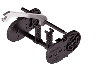
Stay Variants
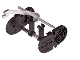
KC0650 RS
Frame stay, narrow "The standard"
- Aluminum profile bars for light to medium loads. Assembly without screws.
- Outside/inside: to open by rotating 90°.
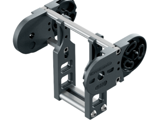
KC0650 LG
Hole stay, split version
- Optimum cable routing in the neutral bending line. Split version for easy cable routing. Stays also available unsplit.
- Outside/inside: Screw-fixing easy to release.
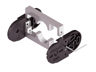
KC0650 RMAI
Mounting frame stay
- Aluminum profile bars with plastic mounting frame stays for guiding very large cable diameters.
- Inside: Screw-fixing easy to release.
KC0650 RMAO
Mounting frame stay
- Aluminum profile bars with plastic mounting frame stays for guiding very large cable diameters.
- Outside: Screw-fixing easy to release.
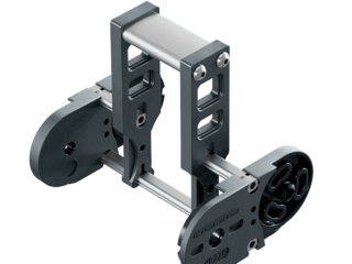
KE0650 RE
Frame screw-in stay
- Plastic profile bars for light to medium loads. Assembly without screws.
- Outside/inside: to open by rotating 90°.
Installation dimensions
UNSUPPORTED ARRANGEMENT

| KR [mm] | H [mm] | Hz [mm] | LB [mm] | UB [mm] |
|---|---|---|---|---|
| 75 | 205 | 245 | 366 | 168 |
| 115 | 285 | 325 | 492 | 208 |
| 145 | 345 | 385 | 586 | 238 |
| 175 | 405 | 445 | 680 | 268 |
| 220 | 495 | 535 | 822 | 313 |
| 300 | 655 | 695 | 1073 | 393 |
LOAD DIAGRAM FOR UNSUPPORTED LENGTH
depending on the additional load.
Sagging of the cable carrier is technically permitted for extended travel lengths, depending on the specific application.
Intrinsic cable carrier weight qk = 2.5 kg/m. For other inner widths, the maximum additional load changes.

Speed
up to 8 m/s

Acceleration
up to 40 m/s2

Travel length
up to 4.8 m

Additional load
up to 20 kg/m

GLIDING ARRANGEMENT

Speed
up to 2 m/s
Acceleration
up to 3 m/s2
Travel length
up to 220 m
Additional load
up to 20 kg/m

The gliding cable carrier must be guided in a channel.
If the cable carrier is positioned so it is rotated by 90° (gliding on the outside of the side band), slide discs snapped onto the side optimize the friction and wear situation.