
S/SX1250
125 mm
66 - 76 mm
130 - 800 mm
145 - 1000 mm
Stay Variants
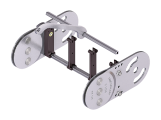
S/SX1250 RS1
Frame stay narrow “The standard”
- Aluminum profile bars for light to medium loads.
- Outside: release by turning by 90°.
- Inside: Threaded joints easy to release.
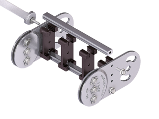
S/SX1250 RS2
Frame stay narrow, bolted
- Aluminum profile bars for light to medium loads. Simple threaded joint.
- Outside/inside: Threaded joints easy to release.
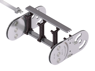
S/SX1250 RV
Frame stay, reinforced
- Aluminum profile bars for medium to heavy loads and large cable carrier widths. Double threaded joint on both sides.
- Inside/outside: Threaded joints easy to release.
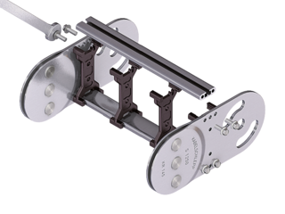
S/SX1250 RM
Frame stay, solid
- Aluminum profile bars for heavy loads and maximum cable carrier widths. Double threaded joint on both sides “Heavy Duty”.
- Inside/outside: Threaded joints easy to release.
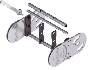
S/SX1250 RR
Frame stay, tube version
- Steel rolling stays with gentle cable support and steel dividers. Ideal for using media hoses with soft sheathing.
- Inside/outside: Screw connection detachable.
S/SX1250 LG
Frame stay, split
- Optimum cable routing in the neutral bending line. Split version for easy cable routing. Stays also available unsplit.
- Inside/outside: Threaded joint easy to release.

S/SX tubes
Also available as covered variants with cover system or steel band cover.
Additional stay variants on request

Aluminium stay RMA
For guiding very large cable diameters

Aluminum stay RMR
Gentle cable guiding with rollers
Installation dimensions
UNSUPPORTED ARRANGEMENT

| KR [mm] | H [mm] | LB [mm] | UB [mm] |
|---|---|---|---|
| 145 | 431 | 955 | 442 |
| 200 | 541 | 1128 | 497 |
| 220 | 581 | 1191 | 517 |
| 260 | 661 | 1317 | 557 |
| 300 | 741 | 1442 | 597 |
| 340 | 821 | 1568 | 637 |
| 380 | 901 | 1694 | 677 |
| 420 | 981 | 1820 | 717 |
| 460 | 1061 | 1945 | 757 |
| 500 | 1141 | 2071 | 797 |
| 540 | 1221 | 2196 | 837 |
| 600 | 1341 | 2385 | 897 |
| 1000 | 2141 | 3640 | 1297 |
Installation height Hz: Hz = H + 10 mm/m
LOAD DIAGRAM FOR UNSUPPORTED LENGTH
depending on the additional load.
Intrinsic cable carrier weight qk = 13 kg/m. For other inner widths, the maximum additional load changes.
Speed
up to 2.5 m/s
Acceleration
up to 5 m/s2
Travel length
up to 13.5 m
Additional load
up to 50 kg/m

GLIDING ARRANGEMENT

Speed
up to 1 m/s
Acceleration
up to 2 m/s2
Travel length
on request
Additional load
up to 50 kg/m
The gliding cable carrier must be guided in a channel.
Glide shoes have to be used for gliding applications.
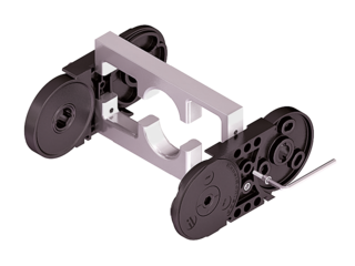
Special designs

S/SX1252 – with closed stroke system and straight link plates
- Closed stroke system protected between link plates mounted on both sides.
- Symmetrical side band design.
- Long service life even under the toughest conditions, e.g. large amounts of foundry sand, emery or scale thanks to optimized cable carrier geometry.

S/SX1252 B – with internal stroke system and straight link plates
- Open stroke system.
- Link plates of the side bands are mounted offset.
- Long service life even under the toughest conditions, e.g. large amounts of foundry sand, emery or scale thanks to optimized cable carrier geometry.
- The optimized, “self-cleaning” geometry prevents blocking of the stops through dirt.
- Version with bolted side bands.