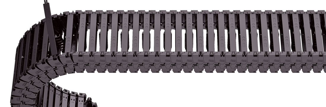
Stay variant 030 – with outside opening and detachable crossbars
Properties
Low-vibration plastic frame with particularly long service life thanks to molded chain links.
Swivable and detachable on one side in any position.
Outside: Swivable and detachable
Inside: detachable
Stay arrangement on each chain link (VS: fully-stayed)
Bi
50 - 200
mm
Dimensions
Dimensions
The maximum cable diameter strongly depends on the bending radius and the desired cable type. Please contact us.
Calculating the cable carrier length
Cable carrier length Lk: Lk ≈ LS/2 + LB
Cable carrier length Lk rounded to pitch t for odd number of chain links
<table class="table">
<thead>
<tr>
<!-- Reihenfolge gemäß Kundenwunsch -->
<th class="t"><strong>t</strong><br>[mm]</th>
<th class="hi red"><strong>h<sub>i</sub></strong><br>[mm]</th>
<th class="hg"><strong>h<sub>G</sub></strong><br>[mm]</th>
<!-- Bi Spalte nur anzeigen wenn einzelner Wert oder Range -->
<!-- Bk und BEF für alle Ketten -->
<th class="bk"><strong>B<sub>k</sub></strong><br>[mm]</th>
<!-- KR Spalte nur anzeigen wenn einzelner Wert oder Range -->
<th class="qk"><strong>q<sub>k</sub></strong><br>[kg/m]</th>
</tr>
</thead>
<tbody>
<tr>
<!-- Reihenfolge gemäß Kundenwunsch -->
<td class="t">28</td>
<td class="hi red">52</td>
<td class="hg">66</td>
<!-- Bi Spalte nur anzeigen wenn einzelner Wert oder Range -->
<!-- Bk und BEF für alle Ketten -->
<td class="bk">Bi + 30</td>
<!-- KR Spalte nur anzeigen wenn einzelner Wert oder Range -->
<td class="qk">2.0 - 3.2</td>
</tr>
</tbody>
</table>
Bi [mm]
50
62
72
87
100
125
150
200
KR [mm]
75
100
150
200
Order example
TKR0280
Type
•
100
Bi [mm]
•
030
Stay variant
•
150
KR [mm]
-
840
Lk [mm]
VS
Stay arrangement
Inner Distribution
Inner Distribution
Divider systems
As standard, the divider system is mounted on every 2nd chain link. As a standard, dividers and the complete divider system (dividers with height separations) can be moved in the cross section (version A).
Fixable dividers are available for applications with lateral accelerations and for applications lying on the side. The arresting cams click into place in the locking grids in the crossbars (version B).
Divider system TS0 without height separation
Vers.
aT min [mm]
ax min [mm]
ac min [mm]
ax grid [mm]
nT min
A
3
8
5.6
–
–
B
A
8
5.6
4
–
A
Bi[mm]
50
62
75
87
100
125
150
200
aT min [mm]
5
7
5.5
3.5
6
6.5
7
4
Divider system TS1 with continuous height separation
Vers.
aT min [mm]
ax min [mm]
ac min [mm]
ax grid [mm]
nT min
A
3
8
5.6
–
2
B
A
8
5.6
4
2
A
Bi[mm]
50
62
75
87
100
125
150
200
aT min [mm]
5
7
5.5
3.5
6
6.5
7
4
Divider system TS3 with height separation made of aluminum partitions
Vers.
aT min [mm]
ax min [mm]
ac min [mm]
ax grid [mm]
nT min
A
3
26
20
–
2
B
A
28
22
4
2
A
Bi[mm]
50
62
75
87
100
125
150
200
aT min [mm]
5
7
5.5
3.5
6
6.5
7
4
The dividers are fixed by the partitions, the complete divider system is movable in the cross section.
<p>Aluminum section subdivisions are only available with <strong>a<sub>x</sub> > 26 mm </strong>.</p>
Order example
TS3
Divider system
•
A
Version
•
3
nT
•
K1
•
K4
Chamber
•
34
•
38
ax
-
VR1
-
VR3
Height separation
End connectors
End connectors
Recommended tightening torque: 0.6 Nm for screws M4
Bi [mm]
BEF [mm]
nz
50
80
2 x 3
62
92
-
75
105
2 x 5
87
117
-
100
130
2 x 7
125
155
2 x 9
150
180
2 x 11
200
230
-
Connection point F – fixed point M– driver
Connection type U – universal mounting bracket
Order example
UMB
UMB
End connector
•
F
•
M
Connection point
U
U
Connection type
We recommend the use of strain reliefs at the driver and fixed point.