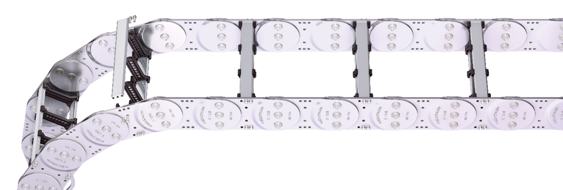
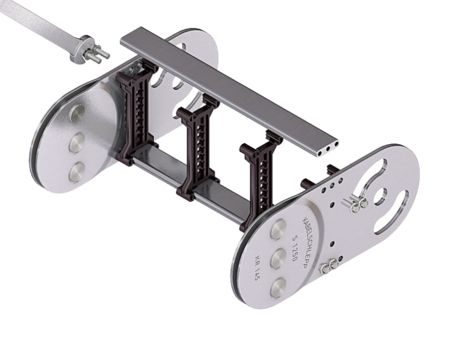
S/SX1250 RV
Aluminum stay RV – reinforced frame stay

Properties
- Aluminum profile bars for medium to heavy loads and large cable carrier widths. Double threaded joint on both sides.
- Available customized in 1 mm grid.
- Inside/outside: Threaded joints easy to release.

Dimensions Dimensions

| KR [mm] | ||||||||||||
|---|---|---|---|---|---|---|---|---|---|---|---|---|
| 145 | 200 | 220 | 260 | 300 | 340 | 380 | 420 | 460 | 500 | 540 | 600 | 1,000 |
Order example
Inner Distribution Inner Distribution
Divider systems
The divider system is mounted on each crossbar as a Standard – on every 2nd chain link for stay mounting (HS).
As a standard, dividers or the complete divider System (dividers with height separations) are movable in the cross section (version A).
Divider system TS0
without height separation
| Vers. | aT min [mm] | ax min [mm] | ac min [mm] | nT min |
|---|---|---|---|---|
| A | 13 | 16 | 10 | – |
The dividers can be moved in the cross section.

Divider system TS1
with continuous height separation
| Vers. | aT min [mm] | ax min [mm] | ac min [mm] | nT min |
|---|---|---|---|---|
| A | 13 | 16 | 10 | 2 |
The dividers can be moved in the cross section.

Divider system TS2
with partial height separation
| Vers. | aT min [mm] | ax min [mm] | ac min [mm] | nT min |
|---|---|---|---|---|
| A | 13 | 21 | 15 | 2 |
With grid distribution (1 mm grid). The dividers are attached by the height separation, the grid can be moved in the cross section.
Sliding dividers are optionally available (thickness of divider = 6 mm).

Divider system TS3
with height separation consisting of plastic partitions
| Vers. | aT min [mm] | ax min [mm] | ac min [mm] | nT min |
|---|---|---|---|---|
| A | 4 | 16/42* | 8 | 2 |
* For aluminum partitions
The dividers are fixed with the partitions. The entire divider system can be moved in the cross section.


Aluminum partitions in 1 mm width increments with ax > 42 mm are also available.
ax (center distance of dividers) [mm] | |||||||||||
ac (nominal width of inner chamber) [mm] | |||||||||||
| 16 | 18 | 23 | 28 | 32 | 33 | 38 | 43 | 48 | 58 | 64 | 68 |
| 8 | 10 | 15 | 20 | 24 | 25 | 30 | 35 | 40 | 50 | 56 | 60 |
| 78 | 80 | 88 | 96 | 112 | 128 | 144 | 160 | 176 | 192 | 208 | |
| 70 | 72 | 80 | 88 | 104 | 120 | 136 | 152 | 168 | 184 | 200 | |
When using plastic partitions with ax > 112 mm, we recommend an additional center support with a twin divider (ST = 4 mm). Twin dividers are also suitable for retrofitting in the partition system.
Order example
Please state the designation of the divider system (TS0, TS1,...), the version, and the number of dividers per cross section [nT]. In addition, please also enter the chambers [K] from left to right, as well as the assembly distances [aT/ax].
When using divider systems with height separation (TS1 – TS3), please additionally state the positions (e.g. VD23) viewed from the left driver belt. You are welcome to add a sketch to your order.
The end dividers are part of the divider system and don‘t have to be ordered separately.
End connectors End connectors


Connection point
F – fixed point
M – driver
Connection type
A – threaded joint outside (standard)
I – threaded joint inside
H – threaded joint, rotated 90° to the outside
K – threaded joint, rotated 90° to the inside
Connection surface
I – connection surface inside (standard)
A – connecting surface outside
Order example
We recommend the use of strain reliefs at the driver and fixed point.
