Q040 RE
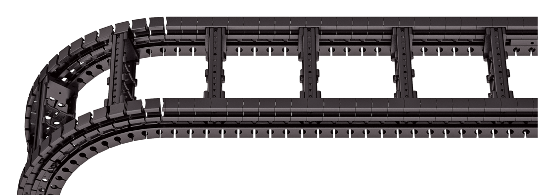
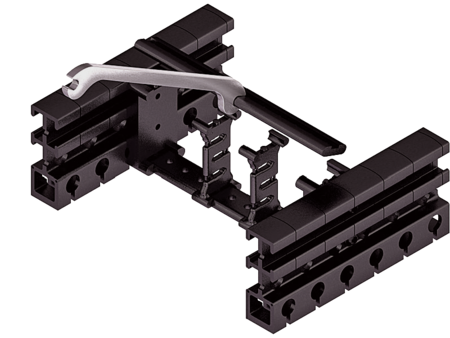
Plastic stay RE – screw-in frame stay

Properties
- Plastic profile bars for light to medium loads. Assembly without screws.
- Available customized in 8 mm sections.
- Outside/inside: release by rotating 90°.

Dimensions Dimensions

| Bi [mm] * | |||||||||
|---|---|---|---|---|---|---|---|---|---|
| 28 | 36 | 44 | 52 | 60 | 68 | 76 | 84 | 92 | 100 |
| 108 | 116 | 124 | 132 | 140 | 148 | 156 | 164 | 172 | 180 |
| 188 | 196 | 204 | 212 | 220 | 228 | 236 | 244 | 252 | 260 |
| 268 | 276 | 284 | |||||||
| KR [mm] | |||||
|---|---|---|---|---|---|
| 60 | 75 | 90 | 110 | 150 | 180 |
Order example
Inner Distribution Inner Distribution
Divider systems
The divider system is mounted on each crossbar as a standard – on every 6th section for stay mounting (HS). As a standard, dividers or the complete divider system (dividers with height separations) are movable in the cross section (version A).
For applications with lateral accelerations and applications with the cable carrier rotated by 90°, the dividers can easily be fixed by turning the frame stay by 180°. The arresting cams click into place in the locking grids in the crossbar (version B). The groove in the frame stay faces outwards.
Divider system TS0
without height separation
| Vers. | aT min [mm] | ax min [mm] | ac min [mm] | ax grid [mm] | nT min |
|---|---|---|---|---|---|
| A | 8 | 8 | 5.2 | – | – |
| B | 14 | 8 | 5.2 | 8 | – |
The dividers are movable within the cross section (version A) or fixed (version B).

Divider system TS1
with continuous height separation
| Vers. | aT min [mm] | aT max [mm] | ax min [mm] | ac min [mm] | ax grid [mm] | nT min |
|---|---|---|---|---|---|---|
| A | 8 | 20 | 8 | 5.2 | – | 2 |
| B | 14 | 22 | 8 | 5.2 | 8 | 2 |
The dividers are movable within the cross section (version A) or fixed (version B).

Divider system TS2
with partial height separation
| Vers. | aT min [mm] | ax min [mm] | ac min [mm] | ax grid [mm] | nT min |
|---|---|---|---|---|---|
| B | 14 | 8*/24 | 5.2*/21.2 | 8 | 2 |
* for VR0
With grid distribution (8 mm grid). The dividers are attached by the height separation, the grid can be moved in the cross section (version A) or fixed (version B).

Order example
End connectors End connectors


Connection point
F – fixed point
M – driver
Connection type
U – universal end connector
Order example
We recommend the use of strain reliefs at the driver and fixed point.
