MT0950 RDD
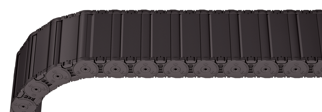
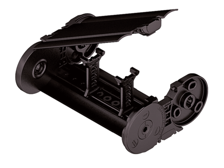
Plastic cover RDD – cover with hinge in the outer radius

Properties
- Plastic cover system with hinge for light and medium loads. Assembly without screws.
- Available customized in 16 mm sections.
- Outside: swivable to both sides.
- Inside: release by turning 90°.

Dimensions Dimensions

| Bi [mm] * | |||||||||
|---|---|---|---|---|---|---|---|---|---|
| 77 | 93 | 109 | 125 | 141 | 157 | 173 | 189 | 205 | 221 |
| 237 | 253 | 269 | 285 | 301 | 317 | 333 | 349 | ||
| KR [mm] | ||||||
|---|---|---|---|---|---|---|
| 140 | 170 | 200 | 260 | 290 | 320 | 380 |
Order example
Inner Distribution Inner Distribution
Divider systems
As a standard, the divider system is assembled at every 2nd chain link.
For applications with lateral acceleration and laying on the side, the dividers or the complete divider system (dividers with height separations) are fixed in the cross section. The arresting cams click into place in the locking grids in the crossbars (version B).
Divider system TS0
without height separation
| Vers. | aT min [mm] | ax min [mm] | ac min [mm] | ax grid [mm] | nT min |
|---|---|---|---|---|---|
| B | 22.5 | 16 | 10 | 16 | – |
The dividers are fixed in the cross section (version B).

Divider system TS1
with continuous height separation
| Vers. | aT min [mm] | aT max [mm] | ax min [mm] | ac min [mm] | ax grid [mm] | nT min |
|---|---|---|---|---|---|---|
| B | 22.5 | 22.5 | 16 | 10 | 16 | 2 |
The dividers are fixed in the cross section (version B).

Divider system TS2
with partial height separation
| Vers. | aT min [mm] | ax min [mm] | ac min [mm] | ax grid [mm] | nT min |
|---|---|---|---|---|---|
| B | 22.5 | 16*/32 | 10*/26 | 16 | 2 |
* for VR0
With grid distribution (16 mm grid). The dividers are fixed by the height separation, the grid is fixed in the cross section (version B).

Divider system TS3
with height separation made of plastic partitions
| Vers. | aT min [mm] | ax min [mm] | ac min [mm] | nT min |
|---|---|---|---|---|
| B | 6.5 | 16/42* | 8 | 2 |
* For aluminum partitions
The dividers are fixed by the partitions, the complete divider system is movable in the cross section.


Aluminum partitions in 1 mm width sections with ax > 42 mm are also available.
ax (center distance of dividers) [mm] | |||||||||||
ac (nominal width of inner chamber) [mm] | |||||||||||
| 16 | 32 | 48 | 64 | 80 | 96 | 112 | 128 | 144 | 160 | 176 | 192 |
| 8 | 24 | 40 | 56 | 72 | 88 | 104 | 120 | 136 | 152 | 168 | 184 |
| 208 | |||||||||||
| 200 | |||||||||||
When using plastic partitions with ax > 112 mm, we recommend an additional center support with a twin divider (ST = 4 mm). Twin dividers are also suitable for retrofitting in the partition system.
Order example
Please state the designation of the divider system (TS0, TS1 …), version and number of dividers per cross section [nT]. In addition, please also enter the chambers [K] from left to right, as well as the assembly distances [aT/ax] (as seen from the driver).
If using divider systems with height separation (TS1, TS3) please also state the positions [e.g. VD23] viewed from the left driver belt. You are welcome to add a sketch to your order.
End connectors End connectors


Connection point
F – fixed point
M – driver
Connection type
U – Universal end connector
Order example
We recommend the use of strain reliefs at the driver and fixed point.


Connection point
F – fixed point
M – driver
Connection type
A – threaded joint outside (standard)
I – threaded joint inside
F – flange connection
Connection surface
A – connection surface outside
I – connection surface inside

Order example
We recommend the use of strain reliefs at the driver and fixed point.
