Skip to main navigation Skip to main content Skip to page footer
MC0950 RMR

MC0950 RMR

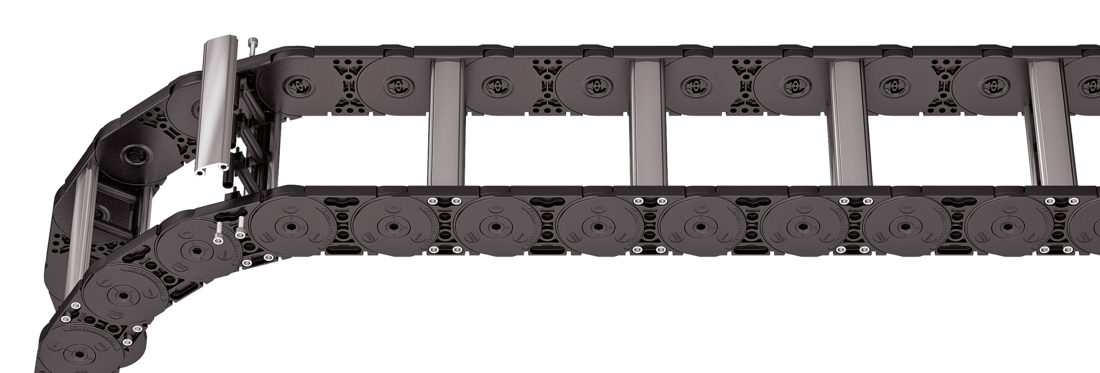
Aluminum stay RMR – Frame rolling stay

Properties

  • Aluminum profile bars with rotating plastic rolling stay for highest requirements with gentle cable guiding. Double threaded joint on both sides.
  • Available customized in 1 mm grid.
  • Inside/outside: Threaded joint easy to release.
Stays on every 2<sup>nd</sup> section, <strong>standard (HS: half-stayed)</strong>
Stay arrangement on each chain link <strong>(VS: fully-stayed)</strong>
Bi 75 - 600 mm in 1 mm width sections

Dimensions Dimensions

The maximum cable diameter strongly depends on the bending radius and the desired cable type. Please contact us.
For rough environmental conditions, we recommend the use of OFFROAD glide shoes with 80 % higher wear volume.
Calculating the cable carrier length
Cable carrier length Lk: Lk ≈ LS/2 + LB
Cable carrier length Lk rounded to pitch t
<table class="table"> <thead> <tr> <!-- Reihenfolge gemäß Kundenwunsch --> <th class="t"><strong>t</strong><br>[mm]</th> <th class="hi red"><strong>h<sub>i</sub></strong><br>[mm]</th> <th class="hg"><strong>h<sub>G</sub></strong><br>[mm]</th> <th class="hgdash"><strong>h<sub>G'</sub></strong><br>[mm]</th> <th class="hgdashoffroad"><strong>h<sub>G'</sub> Offroad</strong><br>[mm]</th> <!-- Bi Spalte nur anzeigen wenn einzelner Wert oder Range --> <th class="bi red"><strong>B<sub>i</sub></strong><br>[mm]<sup>*</sup></th> <!-- Bk und BEF für alle Ketten --> <th class="bk"><strong>B<sub>k</sub></strong><br>[mm]</th> <th class="bef"><strong>B<sub>EF</sub></strong><br>[mm]</th> <th class="dr"><strong>d<sub>R</sub></strong><br>[mm]</th> <th class="st"><strong>ST</strong><br>[mm]</th> <th class="atmin"><strong>a<sub>T</sub> min</strong><br>[mm]</th> <th class="axmin"><strong>a<sub>x</sub> min</strong><br>[mm]</th> <!-- KR Spalte nur anzeigen wenn einzelner Wert oder Range --> <th class="qk"><strong>q<sub>k</sub></strong><br>[kg/m]</th> </tr> </thead> <tbody> <tr> <!-- Reihenfolge gemäß Kundenwunsch --> <td class="t">95</td> <td class="hi red">51</td> <td class="hg">80</td> <td class="hgdash">83.5</td> <td class="hgdashoffroad">86</td> <!-- Bi Spalte nur anzeigen wenn einzelner Wert oder Range --> <td class="bi red"> 75 - 600 </td> <!-- Bk und BEF für alle Ketten --> <td class="bk">Bi + 39</td> <td class="bef">Bi + 39</td> <td class="dr">10</td> <td class="st">4</td> <td class="atmin">6.5</td> <td class="axmin">37</td> <!-- KR Spalte nur anzeigen wenn einzelner Wert oder Range --> <td class="qk">3.63 - 6.55</td> </tr> </tbody> </table>
* in 1 mm width sections
KR [mm]
140 170 200 260 290 320 380

Order example

MC0950
Type
400
Bi [mm]
RMR
Stay variant
200
KR [mm]
-
2850
Lk [mm]
HS
Stay arrangement

End connectors End connectors

Recommended tightening torque: 27 Nm for cheese-head screws ISO 4762 - M8 - 8.8

Connection point
F – fixed point
M – driver

Connection type
U – universal mounting bracket

Order example

UMB
UMB
End connector
F
M
Connection point
U
U
Connection type

We recommend the use of strain reliefs at the driver and fixed point.

Connection point
F – fixed point
M – driver

Connection type
A – threaded joint outside (standard)
I – threaded joint inside

Connection surface
I – connection surface inside
A – connection surface outside

Order example

Plastic/steel
Plastic/steel
End connector
F
M
Connection point
A
A
Connection type
A
I
Connection surface

We recommend the use of strain reliefs at the driver and fixed point.