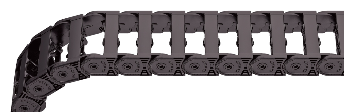
Stay variant 040 – with lamellae in the inner radius
Properties
Weight-optimised plastic frame with particularly high torsional rigidity.
Lamellae can be swivelled at any position on one side
Inside: swivelling.
Stay arrangement on each chain link (VS: fully-stayed)
Bi
15 - 65
mm
Dimensions
Dimensions
The maximum cable diameter strongly depends on the bending radius and the desired cable type. Please contact us.
Design 040 is not suitable for gliding arrangements.
Calculating the cable carrier length
Cable carrier length Lk: Lk ≈ LS/2 + LB
Cable carrier length Lk rounded to pitch t
<table class="table">
<thead>
<tr>
<!-- Reihenfolge gemäß Kundenwunsch -->
<th class="t"><strong>t</strong><br>[mm]</th>
<th class="hi red"><strong>h<sub>i</sub></strong><br>[mm]</th>
<th class="hg"><strong>h<sub>G</sub></strong><br>[mm]</th>
<!-- Bi Spalte nur anzeigen wenn einzelner Wert oder Range -->
<!-- Bk und BEF für alle Ketten -->
<th class="bk"><strong>B<sub>k</sub></strong><br>[mm]</th>
<!-- KR Spalte nur anzeigen wenn einzelner Wert oder Range -->
<th class="qk"><strong>q<sub>k</sub></strong><br>[kg/m]</th>
</tr>
</thead>
<tbody>
<tr>
<!-- Reihenfolge gemäß Kundenwunsch -->
<td class="t">32</td>
<td class="hi red">18</td>
<td class="hg">25.5</td>
<!-- Bi Spalte nur anzeigen wenn einzelner Wert oder Range -->
<!-- Bk und BEF für alle Ketten -->
<td class="bk">Bi + 12</td>
<!-- KR Spalte nur anzeigen wenn einzelner Wert oder Range -->
<td class="qk">0.35 – 0.45</td>
</tr>
</tbody>
</table>
Bi [mm]
15
25
38
50
65
KR [mm]
28
38
48
75
100
125
Order example
ET0320
Type
•
040
Stay variant
•
50
Bi [mm]
•
100
KR [mm]
-
1280
Lk [mm]
VS
Stay arrangement
Inner Distribution
Inner Distribution
Divider systems
The divider system is mounted on every 2nd chain link as a standard.
As a standard, dividers or the complete divider system (dividers with height separations) are movable in the cross section (version A).
Divider system TS0 without height separation
Vers.
aT min [mm]
ax min [mm]
ac min [mm]
nT min
A
4
8
6
–
The dividers can be moved in the cross section.
Order example
TS0
Divider system
•
A
Version
•
3
nT
Please state the designation of the divider system (TS0), the version, and the number of dividers per cross section [nT]. You are welcome to add a sketch to your order.
End connectors
End connectors
Bi [mm]
BEF [mm]
nz
15
27
2
25
37
3
38
50
4
50
62
5
65
77
6
The end connectors are also available as an option without integrated strain relief. Please state when ordering.
Connection point F – fixed point M– driver
Connection type A – threaded joint outside (standard) I – threaded joint inside H – threaded joint, rotated 90° to the outside K – threaded joint, rotated 90° to the inside