
XLT1650
XLT1650
Pitch
165 mm
165 mm
Inner height
105 mm
105 mm
Inner widths
200 - 1000 mm
200 - 1000 mm
Bending radii
300 - 550 mm
300 - 550 mm
Stay Variants
XLT1650 RMD
more details
Stay Variants
XLT1650 RMD
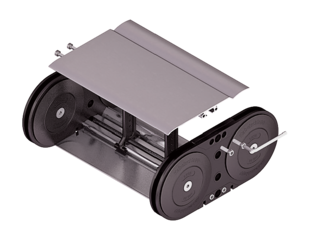
Aluminum cover system
- Bolted aluminum covers for maximum stability
- For applications generating swarf or coarse contamination
- Inside/outside: Threaded joint easy to release.
Installation dimensions


Installation dimensions
UNSUPPORTED ARRANGEMENT
| KR [mm] | H [mm] | Hz [mm] | LB [mm] | UB [mm] |
|---|---|---|---|---|
| 300 | 740 | 840 | 1272 | 535 |
| 350 | 840 | 940 | 1430 | 585 |
| 400 | 940 | 1040 | 1587 | 635 |
| 450 | 1040 | 1140 | 1744 | 685 |
| 500 | 1140 | 1240 | 1901 | 735 |
| 550 | 1240 | 1340 | 2058 | 785 |
LOAD DIAGRAM FOR UNSUPPORTED LENGTH
depending on the additional load.
Sagging of the cable carrier is technically permitted for extended travel lengths, depending on the specific application.
Intrinsic cable carrier weight qk = 13 kg/m. For other inner widths, the maximum additional load changes.
Speed
up to 4 m/s
Acceleration
up to 25 m/s2
Travel length
up to 11.75 m
Additional load
up to 65 kg/m
GLIDING ARRANGEMENT
Speed
up to 2 m/s
Acceleration
up to 2-3 m/s2
Travel length
up to 350 m
Additional load
up to 65 kg/m
The gliding cable carrier must be guided in a channel.
We recommend the use of glide shoes for gliding applications.