Aluminum Channel
Aluminum guide channels
Properties
- Version made from aluminum profiles.
- Low intrinsic weight.
- Standard lengths.

Channel side wall
Al alloy

Standard lengths for channel side wall 2000 mm
Standard lengths for clamping profile 130 mm
Pictographs
 Inner height
 Outer height
 Inner width
 Outer width
 Inner width (Bi) in x mm increments
 Pitch
Pitch
 Bending radius
 Long travel length
 Travel length unsupported
 Travel length gliding
 High additional load
 High travel acceleration
 High travel velocity
 Stay arrangement on every 2nd chain link
 Stay arrangement on every chain link
 Cannot be opened
 Opens outward
 Opens inward
 Opens inward/outward
 Covered cable carrier
 Sliding dividers
 Fixable dividers
 Fixable dividers in x mm grid
 Height separation possible
 Height separation in 1 mm increments
 Hole stay available
 Guide channel required
 Strain relief
 Clean room suitable
 Quiet running/low noise
 Sold by the meter
 Low weight
 ESD material
 Ex-protection-material
 Heat-resistant
 Cold-resistant
 Resistant to hot chips
 Flame-resistant V0 (UL94)
 Flame-resistant V2 (UL94)


Features
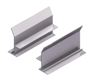
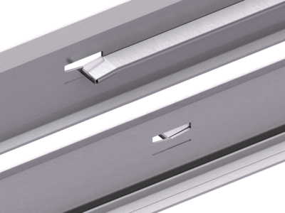
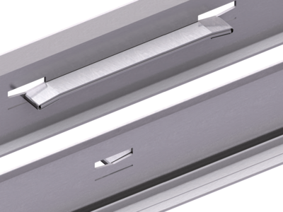
- No screw connections on joins, alignment through double clamping connection with plastic clamping profiles
- Available with continuous bottom panel on request
- Easy handling
- Low intrinsic weight
- One part channel side walls
- Channel side wall profiles with support, with start-up bevel on both sides
Versions
One-sided arrangement
For one-sided arrangement of the cable carrier, the cable carrier slides behind the fixed point on a continuous slide support with run-off bevels.
Open design
Channel profile with and without supports incl. run-on bevels.
Dirt and water can drop through without restrictions.
Opposite arrangement
For opposite arrangement, a slide support is also attached for bridging between the fixed point connections.
Open design
Channel profile with and without supports incl. run-on bevels.
Dirt and water can drop through without restrictions.
Dimensions

Design A – without slide support

Design A – with slide support

Design B – without slide support

Design B – with slide support
MONO series
The cable carrier outer width without attachments Bk is taken into account for calculating the inner width of guide channel b1 and the overall width BKA.
| Type | Design | h1 [mm] | h2 [mm] | hKA [mm] | b1 [mm] | b2 [mm] | BKA [mm] | s1 [mm] | s2 [mm] | D [mm] | ||||
|---|---|---|---|---|---|---|---|---|---|---|---|---|---|---|
| 0130/0132 | ||||||||||||||
| – | A | 18 | 1.5 | 38 | Bk + 3 | Bk + 16 | BK + 26 | 1.5 | – | 6 | ||||
| 0180/0182 | ||||||||||||||
| – | A | 18 | 1.5 | 38 | Bk + 3 | Bk + 16 | BK + 26 | 1.5 | – | 6 | ||||
| 0202 | ||||||||||||||
| – | A | 18 | 1.5 | 38 | Bk + 3 | Bk + 16 | BK + 26 | 1.5 | – | 6 | ||||
QuickTrax® series
The cable carrier outer width without attachments Bk is taken into account for calculating the inner width of guide channel b1 and the overall width BKA.
| Type | Design | h1 [mm] | h2 [mm] | hKA [mm] | b1 [mm] | b2 [mm] | BKA [mm] | s1 [mm] | s2 [mm] | D [mm] | ||||
|---|---|---|---|---|---|---|---|---|---|---|---|---|---|---|
| QT0320 | ||||||||||||||
| – | B | 27.5 | 1.5 | 55 | Bk + 3 | Bk + 29 | BK + 42 | 1.5 | – | 7 | ||||
UNIFLEX Advanced series
The cable carrier outer width without attachments Bk is taken into account for calculating the inner width of guide channel b1 and the overall width BKA.
| Type | Design | h1 [mm] | h2 [mm] | hKA [mm] | b1 [mm] | b2 [mm] | BKA [mm] | s1 [mm] | s2 [mm] | D [mm] | ||||
|---|---|---|---|---|---|---|---|---|---|---|---|---|---|---|
| UA1320 | ||||||||||||||
| – | B | 27.5 | 1.5 | 55 | Bk + 3 | Bk + 29 | BK + 42 | 1.5 | – | 7 | ||||
EasyTrax® series
The cable carrier outer width without attachments Bk is taken into account for calculating the inner width of guide channel b1 and the overall width BKA.
| Type | Design | h1 [mm] | h2 [mm] | hKA [mm] | b1 [mm] | b2 [mm] | BKA [mm] | s1 [mm] | s2 [mm] | D [mm] | ||||
|---|---|---|---|---|---|---|---|---|---|---|---|---|---|---|
| ET0180 | ||||||||||||||
| – | A | 18 | 1.5 | 38 | Bk + 3 | Bk + 16 | BK + 26 | 1.5 | – | 6 | ||||
| ET0320.030 | ||||||||||||||
| – | B | 27.5 | 1.5 | 55 | Bk + 3 | Bk + 29 | BK + 42 | 1.5 | – | 7 | ||||
M series
The cable carrier outer width without attachments Bk is taken into account for calculating the inner width of guide channel b1 and the overall width BKA.
| Type | Design | h1 [mm] | h2 [mm] | hKA [mm] | b1 [mm] | b2 [mm] | BKA [mm] | s1 [mm] | s2 [mm] | D [mm] | ||||
|---|---|---|---|---|---|---|---|---|---|---|---|---|---|---|
| M0320 | ||||||||||||||
| – | B | 27.5 | 1.5 | 55 | Bk + 3 | Bk + 29 | BK + 42 | 1.5 | – | 7 | ||||
TKA series
The cable carrier outer width without attachments Bk is taken into account for calculating the inner width of guide channel b1 and the overall width BKA.
| Type | Design | h1 [mm] | h2 [mm] | hKA [mm] | b1 [mm] | b2 [mm] | BKA [mm] | s1 [mm] | s2 [mm] | D [mm] | ||||
|---|---|---|---|---|---|---|---|---|---|---|---|---|---|---|
| TKA30 | ||||||||||||||
| – | B | 27.5 | 1.5 | 55 | Bk + 3 | Bk + 29 | BK + 42 | 1.5 | – | 7 | ||||
Fixing Elements
Screw connection from “outside”
Fixing holes are drilled for this purpose. A marking groove facilitates alignment and drilling.


Calculating C-profile length
Order
To order the Aluminium channel , please provide the following information:
- Number of guide channels
- Total length of channel
- Support length LKA'
- Ouer height of guide channel hKA
- Inner width of guide channel b1
- Support height h1
- Design