Q100 RS
Aluminum stay RS – frame stay narrow
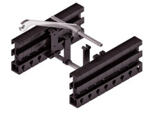
Properties
- Extremely quick to open and close.
- Aluminum profile bars for light to medium loads. Assembly without screws.
- Available customized in 1 mm sections.
- Outside/inside: release by rotating 90°.

Stays on every 8th section, standard (HS: half-stayed)

Stays on every 4th section (VS: fully-stayed)

Pictographs
 Inner height
 Outer height
 Inner width
 Outer width
 Inner width (Bi) in x mm increments
 Pitch
Pitch
 Bending radius
 Long travel length
 Travel length unsupported
 Travel length gliding
 High additional load
 High travel acceleration
 High travel velocity
Stay arrangement on every 2nd chain link
Stay arrangement on every chain link
High travel velocity
Stay arrangement on every 2nd chain link
Stay arrangement on every chain link
 Cannot be opened
 Opens outward
 Opens inward
 Opens inward/outward
 Covered cable carrier
 Sliding dividers
 Fixable dividers
 Fixable dividers in x mm grid
 Height separation possible
 Height separation in 1 mm increments
 Hole stay available
 Guide channel required
 Strain relief
 Clean room suitable
 Quiet running/low noise
 Sold by the meter
 Low weight
 ESD material
 Ex-protection-material
 Heat-resistant
 Cold-resistant
 Resistant to hot chips
 Flame-resistant V0 (UL94)
 Flame-resistant V2 (UL94)


Dimensions
The maximum cable diameter strongly depends on the bending radius and the desired cable type. Please contact us.
Calculating the cable carrier length

hi
[mm]
|
hG
[mm]
|
hG'
[mm]
|
Bi
[mm]
* |
Bk
[mm]
|
BEF
[mm]
|
qk
[kg/m]
|
|---|---|---|---|---|---|---|
| 72 | 98 | 108 | 70 – 600 | Bi + 82 | Bi + 89.5 | 2.60 – 3.40 |
KR
[mm]
| |||||
|---|---|---|---|---|---|
| 180 | 250 | 300 | 370 | 460 | 600 |
Order example
Q100
400
RS
370
1860
HS
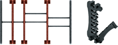
Inner distribution
The divider system is mounted on each crossbar as a standard – on every 8th section for stay mounting (HS).
As a standard, dividers or the complete divider system (dividers with height separations) are movable in the cross section (Version A).
For applications with lateral acceleration and rotated by 90°, the dividers can be attached by simply clipping onto a socket (available as an accessory).
The socket additionally acts as a spacer between the dividers and is available in 1 mm increments between 3 – 50 mm (Version B).

| Vers. |
aT min
[mm]
|
ax min
[mm]
|
ac min
[mm]
|
nT min |
|---|---|---|---|---|
| A | 11 | 15 | 10 | 2 |
The dividers can be moved in the cross section.

| Vers. |
aT min
[mm]
|
aT max
[mm]
|
ax min
[mm]
|
ac min
[mm]
|
nT min |
|---|---|---|---|---|---|
| A | 11 | 25 | 15 | 10 | 2 |
The dividers can be moved in the cross section.
As a standard, the divider version A is used for vertical partitioning within the cable carrier. The complete divider system can be moved within the cross section.
Divider version A
End divider


| Vers. |
aT min
[mm]
|
ax min
[mm]
|
ac min
[mm]
|
nT min |
|---|---|---|---|---|
| A | 10.5/6.5* | 14 | 10 | 2 |
* for End divider
The dividers are fixed by the partitions, the complete divider system is movable in the cross section.

| ax (center distance of dividers) [mm] | ||||||||||||||||||||||
|---|---|---|---|---|---|---|---|---|---|---|---|---|---|---|---|---|---|---|---|---|---|---|
| ac (nominal width of inner chamber) [mm] | ||||||||||||||||||||||
16 8 | 18 10 | 23 15 | 28 20 | 32 24 | 33 25 | 38 30 | 43 35 | 48 40 | 58 50 | 64 56 | 68 60 | 78 70 | 80 72 | 88 80 | 96 88 | 112 104 | 128 120 | 144 136 | 160 152 | 176 168 | 192 184 | 208 200 |
When using partitions with ax > 49 mm we recommended an additional preferential central support.
Order example
TS3
A
3
K1
K4
34
38
VR1
VR3
Please state the designation of the divider system (TS0, TS1,...), version and number of dividers per cross section [nT ]. In addition, please also enter the chambers [K] from left to right, as well as the assembly distances [aT/ax] (as seen from the driver).
If using divider systems with height separation (TS1 – TS3), please also state the positions [e.g. VD23] viewed from the left driver belt. You are welcome to add a sketch to your order.
End connectors
Universal connection element UMB - plastic (standard)
The universal end connectors (UMB) are made from plastic and can be mounted from the top, from the bottom, face on or from the side.
F – fixed point
M – driver
U – universal end connector
Order example
UMB
F
U
UMB
M
U
UMB
UMB
F
M
U
U
We recommend the use of strain reliefs at the driver and fixed point.